
GP1527 8F box
Introduction
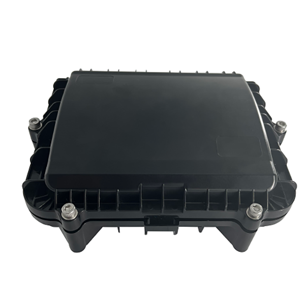
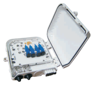
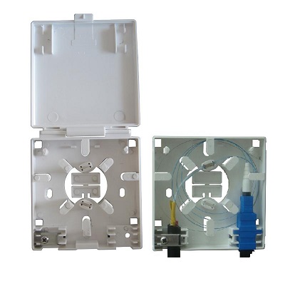
This box offer a durable, compact solution with multiple internal fiber organizers to support your current and future needs. Constructed out of rugged UV-stabilized, flame-retardant material and the metal parts inside the box are made of SUS304 material. Sealed with high-performance silicone rubber strips, can effectively prevent the inner space from rain and dust, available for indoor, outdoor, aerial wall, and pole mounting.
Specification
| Model | Splice capacity | Dimension
mm |
Port number | Available cable dia. | Adapter number | Splitter type | Raw material |
| GP1527 | 12F/24F
Max. 1 tray |
190*224*72 | With 2 large silicone grommets ( 1big holes + 6 small holes) and 2 small silicone grommets ( 2small holes) | Big holes for 12-16mm cable
Small holes for 3-6mm cable |
8 simplex SC , FC or 4 Dual SC or 4 Quad LC adapters | Micro PLC splitter 1:4 or 1:8 | PC/ABS
|
Technical Parameter
Working Temperature::-25℃~+55℃
Environmental humidity:≤85%(+30℃)
Atmospheric Pressure::70kPa~106kPa
Optoelectronic performance:Insert Loss≤0.2dB Return Loss ≥50dB Connection Loss≤0.5dB
Insulation resistance ≥1000MΩ500V(DC)
Voltage Strength::Can withstand 3000V (DC) for 1 minute without breakdown/arcing phenomenon

Port sealing rubber
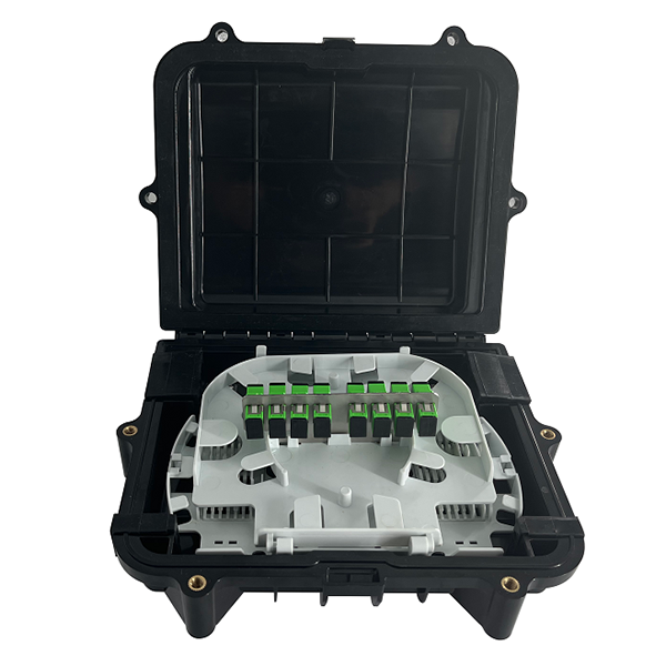
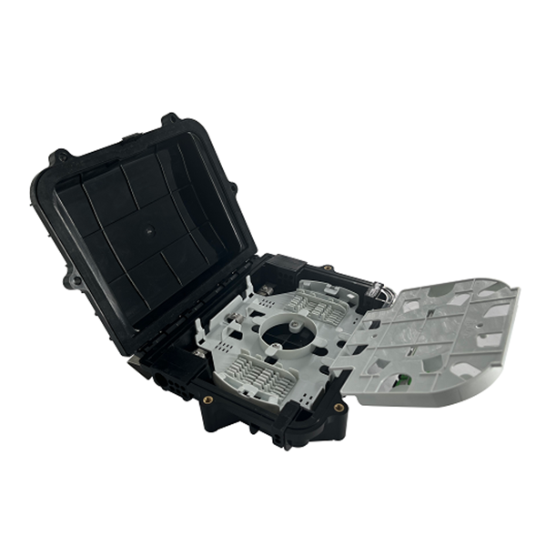
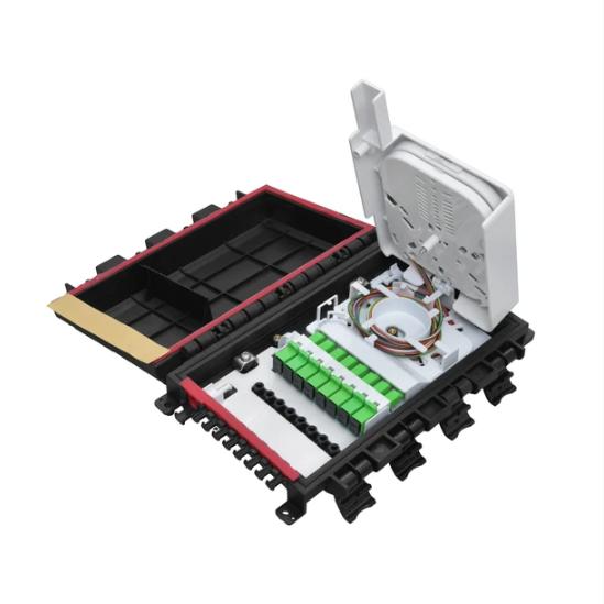
Structural Diagram
Equipped with a hinged adapter bulkhead that allows access to the underlaying fiber splice tray. A 1:4 or 1:8 micro PLC connectorized or non-connectorized splitter can be placed in the splitter block.


Main components
| Item | Name | Qty | Function | Photo |
| 1 | Box body | 1set | Protect the inner cables | 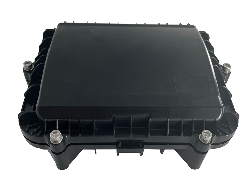 |
| 2 | Optic Splice tray | 1pc | Splice and store the bare fibers | 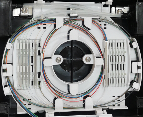 |
| 3 | Fiber storage tray | 1pc | Store fibers and pigtail wires | 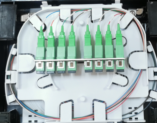 |
| 4 | Cable attach plate | 3sets | Fixing the sheath stripped cable | 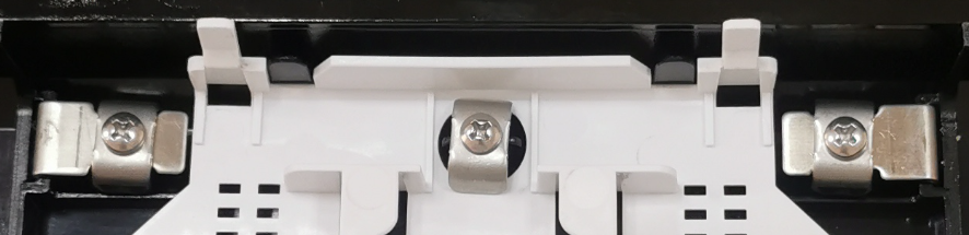 |
| 5 | Adapter nut | 1pc | Hold adapters | 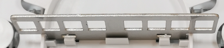 |
Main accessories
| Item | Name | Qty | Function | Photo |
| 1 | Optic joints protective tubes | Based on capacity | to protect optic fiber joints |  |
| 2 | PE tube | Based on capacity | to protect the bare cables | 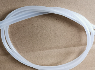 |
| 3 | Nylon tie | Based on capacity | Tie the PE tube | 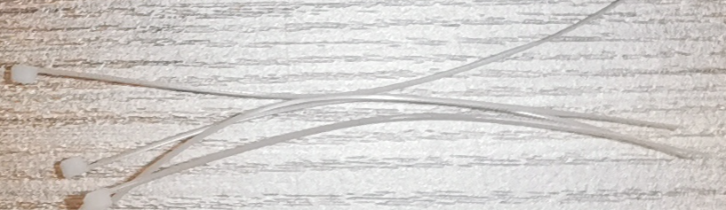 |
| 4 | Wall mounting kits (optional) | 4pcs | Wall mounting | 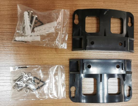 |
| 5 | Hose clamp | 2pcs | Fix the cable inside the box | 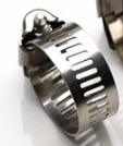 |
| 6 | Pole mounting kits(optional) | 2pcs | To fix the box on pole | 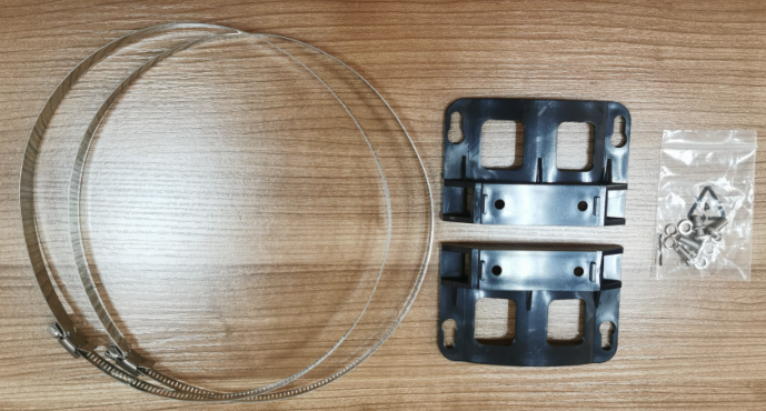 |
| 7 | Aerial mounting kits (optional) | 1 set | To fix the box overhead | 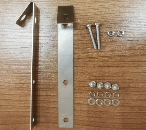 |
| 8 | 1:8 or 1:4 micro PLC splitter (optional) | 8 PCS | Order in additional | |
| 9 | Adapter(optional) | 8PCS | Order in additional |
Installation guidance
1.Cut the edge of the silicon grommet rubber Put the cable through the rubber, then sheath strip the cable in 1.5m length. Reserve about 10 mm of the cable strengthen wire and bend it to hook on the screw under the clip and tighten the screw.

2.Thread the peeled optical buffer tube through the PE tube and use PVC tape to wrap the joint place to fix the PE tube on the cable. Coil the PE tube twice along the winding reel before introducing the bare fibers into splice tray Tie the PE tube edge at the entry place of the splice tray. Winding the excessive length of the bare fiber to store it inside the splice tray. Based on project requirement, install the required splitter and adapters, Then fusion the fibers with the fiber ends from the splitter or branch-off cables. Adjust the different optical cables inside the box to ensure a smooth and beautiful fiber route.


Application

Pole mounting

Aerial mounting

Wall mounting

-

Phone
-

E-mail
-

Whatsapp
-

Top